
Can Autonomous Haulage Vehicles Stay Connected Underground?
2026.10.23 / By Sailsky
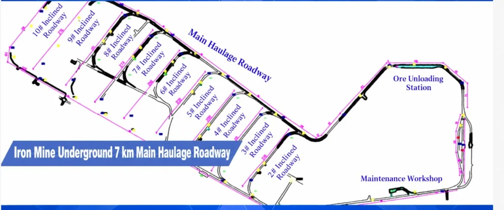
An iron mine deployed an autonomous haulage system along a 7 km underground main haulage roadway. The documented communications scope covered 12 autonomous rail vehicles and combined a redundant fibre backbone with continuous wireless coverage and vehicle-mounted CPE clients.
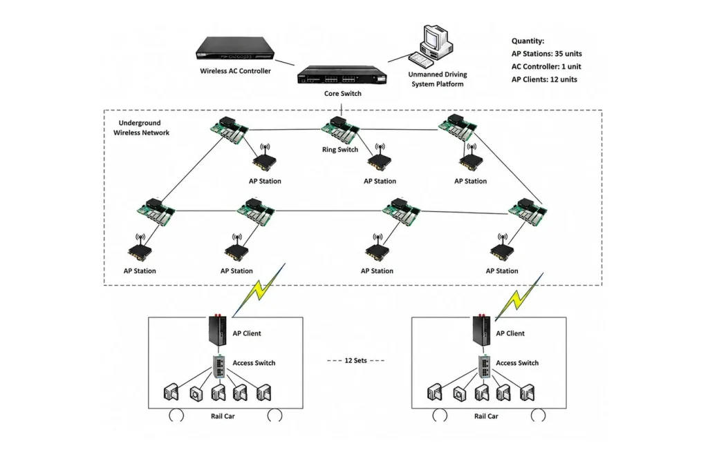
The verified project configuration included 35 wireless AP base stations, one wireless AC controller and 12 vehicle CPEs. This underground mine wireless network carried dispatch and control commands together with vehicle status, sensor data and video traffic from four 4 MP cameras on each rail vehicle. Actual performance depends on the site conditions.
Project requirements in a long underground roadway
The haulage roadway is long and narrow, with bends, junctions, rock strata and metal structures that can attenuate, reflect or obstruct radio signals. Moving vehicles also need to transition between access points without a long interruption to communications used by the autonomous-driving and dispatch systems.
- Continuous wireless coverage along a 7 km underground main haulage roadway.
- Wireless access for 12 rail vehicles while they are in motion.
- Concurrent transmission of control commands, vehicle status, sensor data and video traffic.
- Equipment selection suited to dust, vibration and applicable underground mine-safety requirements.
Underground mine wireless network architecture
The project used a converged architecture of a wireless AC controller, core switch, underground ring switches, industrial wireless access points and vehicle CPE clients. This wireless network architecture created an end-to-end communication path between the autonomous-driving system platform and the underground route.
Redundant fibre backbone
The wireless AC controller and autonomous-driving platform connected through a core switch. Underground ring switches used redundant fibre-ring connections with backbone bandwidth above 1,000 Mbps. The redundant path was intended to reduce the effect of a single link or node failure on communications.
Continuous coverage and vehicle roaming
Thirty-five AP base stations were planned along the route according to roadway geometry, vehicle movement and equipment distribution. Directional antennas controlled signal propagation. The design strengthened coverage at bends and junctions, and the documented adjacent-cell overlap was at least 20% to support handover.
Each rail vehicle used one vehicle-mounted CPE (onboard wireless client) and an onboard access switch for the vehicle controller, sensors and other onboard equipment. Project records state cross-AP roaming below 20 ms with zero-packet-loss handover and available terminal bandwidth above 50 Mbps per vehicle. These are documented project results, not universal product guarantees.
Deployment and acceptance checks
The project workflow included a route and fibre-resource survey, network and antenna planning, equipment installation, coverage optimisation and integrated testing. On-site adjustments focused on bends, junctions and obstructed areas. Acceptance checks included vehicle roaming, link redundancy, service bandwidth, and continuity of control and sensor traffic.
The ordered configuration must be confirmed before deployment. Coverage, throughput and roaming behaviour require an on-site survey and acceptance test for every new mine.
Verified project indicators
| Indicator | Verified project value |
| Main haulage roadway | 7 km |
| Wireless AP base stations | 35 |
| Wireless AC controller | 1 |
| Vehicle-mounted CPE (onboard wireless client) / rail vehicles | 12/12 |
| Backbone bandwidth | Above 1,000 Mbps |
| Adjacent AP overlap | At least 20% |
| Cross-AP roaming | Under 20 ms |
| Roaming data transmission | Zero-packet-loss handover |
| Per-vehicle terminal bandwidth | Above 50 Mbps |
Project outcome and planning considerations
For this documented project, route-based AP planning, controlled overlap, vehicle clients and the redundant fibre ring supported continuous communications along the 7 km route for 12 autonomous rail vehicles. The system carried dispatch commands, remote-control traffic, sensor data and vehicle status. The results apply to this project only.
For a comparable project, a mine wireless coverage solution should begin with the roadway layout, route length, bends and junctions, vehicle count, traffic types, existing fibre resources and applicable mine-safety requirements. Sailsky can assess the access, roaming and backbone scope against the actual site conditions.